Basic scooter components
The following animation will give you an overview of the scooter’s main components. You may stop any time to compare the numbers displayed with the drawing below:

1 – Cap nut
The cap nut fixes the housing lid [5] to the center rod [8], thus making the scooter watertight, if properly tightened. The cap nut is sealed by 2 o-rings [2 / 3].
2 / 3 – Cap nut o-rings
These o-rings seal the cap nut against the housing lid.
They need to be exchanged during regular service.
4 – Multipurpose transport bracket
This special transport bracket supports the scooter when placed on a flat surface, it allows for simple carrying of the scooter, and it provides several attachement points for accessories.
5 – Housing lid
The housing lid covers the internal scooter part. It is fixed to the center rod [8] of the drive unit [15] by means of the cap nut [1]. The housing lid is sealed against the drive unit by 3 o-rings [11 / 12].
6 – Battery segment fixation nut
This nut holds the battery segment fixation ring [7] on the center rod [8] and thus the battery segments in place. Make sure to always install this nut hand-tight, to avoid any movement of the battery segments.
7 – Battery segment fixation ring
This ring is held in place by the battery segment fixation nut [6]. If the openings in this ring are properly placed over the installed battery segments, and if the battery segment fixation nut is tightened, the battery segments cannot move inside the scooter and will thus provide the energy stored inside without any interruption.
8 – Center rod
This rod serves as the “backbone” of the scooter, providing a mechanical link between cap nut, housing lid, battery segments and drive unit. The center rod may be removed by the user in order to facilitate travelling.
9 – Guiding opening for center rod
The center rod is inserted into this opening in order to provide stability.
10 – Battery disconnector
This disconnector is placed in a free slot on the upper side of the battery segment contacts.
By means of this disconnector, the user may interrupt the connection betwen the battery segments and the engine / control system. This is highly recommended e.g. for shipping the scooter, in order to comply to the transportation rules for LI-ion batteries. Please note, that the dsconnector must be in place in order to charge the battery segments.
11 – Lid o-rings
The 2 lid o-rings touch the inner part of the housing lid [5] and make it watertight. These o-rings have to be exchanged during regular service.
12 – Drive unit o-ring
This o-ring touches the lower edge of the housing lid [5] and serves as additional seal. This o-ring has to be exchanged during regular service.
13 – Securing pin
This pin serves to hold the center rod [8] in the guiding opening [9].
14 – Moveable fixation element
This element is part of the intrinsic scooter safety concept.
15 – Drive unit
The drive unit holds all propulsion-related components of the scooter, meaning the control system and the engine.
16 – Main switch
The scooter is equipped with a non-contact sensor responsible for turning the device on and off. Operating the scooter in SWITCHED OFF mode is characterized by very low power consumption, so it is not necessary to unclip the battery from the scooter after each use, and thus it is not necessary to disassemble the scooter every time it has been used.
It may be turned in any direction in order to swith the scooter on (switch positioned in direction of travel) or off (switch positioned perpendicular to the direction of travel).
17 – Sports camera mount
This standard holder allows for attaching a sports camera or the Seacraft Electronic Navigation Console to the scooter.
18 – Control trigger
The scooter provides 2 control triggers, which need to be pressed (depending on the selected drive mode) independently or at the same time.
19 – Steering handle
The scooter provides 2 steering handles with integrated control triggers [19].
These handles allow for steering the scooter into the desired direction.
20 – Nozzle
The nozzle directs the water flow to the propeller and away from it. It also holds the pre-swirl stator, which eliminates all torque forces created by the rotating propeller, and offers 4 harness attachment points.
21 – Charging contacts cap
This cap protects the charging contacts from contamination, if the scooter is not in use.
22 – Charging contacts
This scooter may be charged without opening it. Simply wipe these specially coated, corrosion-proof contacts clean / dry, and connect the supplied charger as stated in the manual. The charging contacts are secured by diodes, so there will be no electrical current flow through these contacts, when the charger is not connected.
23 – Trim weights
The trim system of this scooter allows for continously adjusting the trim, by moving the trim weighs back and forth by means of two setting screws [24]. Like this, you may adapt the scooter to changing water salinity and / or accessories, so it will stay level underwater.
24 – Trim weight screws
By means of these 2 screws, the user may move the installed trim weights [23] continuously back and forth on the trim weight rod [25].
25 – Trim weight rod
The trim weights [23] are placed in a free slot on the lower side of the battery segment contacts. Like this, the trimming system also serves as a “keel” for the scooter, keeping the steering handles pointing upwards underwater.
26 – Propeller
The propeller rides on the magnetic field generated by the engine’s stator. It is held in place by magnetic forces and may by simply pulled off in case of an entanglement etc.
Display

1 – Control buttons
With these piezoelectric buttons, the user may select the desired gear while the engine is stopped or running.
2 – Left LED strip (gears)
These LEDs show the currently selected gear.
Blue LEDs show the forward gears (1-8), a red LED shows, that the reverse gear is selected. If no LED is lit, the engine will not start, when the user presses a control trigger.
3 – Right LED strip (charging level / mode)
These LEDs show the current charging level of the installed battery segments (approx. 11 % per LED) or (during setting the drive mode) the currently selected mode: Sports mode (yellow), Expert mode (red) or Freediving mode (green).
Drive unit
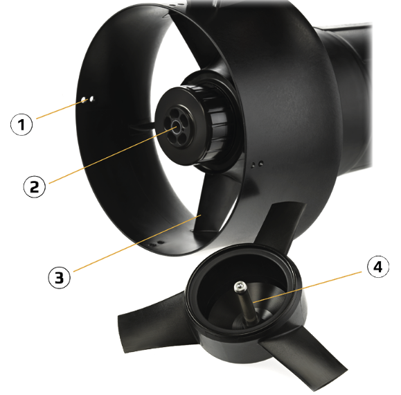
1 – Harness attachement points in the nozzle
The nozzle provides 4 harness attachement points (left / right, top / bottom).
The provides scooter harness is attached here, so the diver will be pulled by the scooter via the harness carabiner attached to the crotch belt.
2 – Fixed engine part with bushings
This scooter provides a patented magnetic drive, where the engine is outside the scooter, working “in the water”. Like this, all mechanical links to an internal electrical motor are eliminated. The fixed part (“stator”) is mounted inside the nozzle. It provides a guide bushing, so the engine rotor with propeller [4] can rotate freely around it (powered by the magnetic field of the stator).
3 – Pre-swirl stator
This scooter may be driven “with 2 fingers only”, because all torque effects created by the rotating propeller are eliminated (independently of the selected gear). To reach this goal, the pre-swirl stator transforms the water flow into thrust.
4 – Rotor with propeller
This engine part rotates on the created magnetic field around the fixed engine part [2], while the little ball on the tip of the axle is the only point of contact between the rotating part and the rest of the scooter. For this reason, this scooter is very energy-efficient.
Electronics
Motor controller
The brushless motor (BLAC, BrushLess Alternating Current) controller’s task is to produce a three-phase voltage which is used to power the motor. The motor controller communicates with the display and control module in order to obtain information about the chosen gear and transmits information on operating parameters of the scooter display module e.g. the state of the battery, propeller speed, the electricity consumed by the scooter, battery voltage, etc.
Control electronics
The control electronics is an interface, relaying the user’s actions to the scooter.
Battery with control system
The scooter is powered by a battery made up of rechargeable lithium-ion segments. The scooter battery voltage is always in a safe range for the user. The battery is equipped with a BSM system (Battery Management System), which compensates the voltage across all the cells and a PCM system (Protection Circuit Module) that protects the battery against overload, overcharging and excessive discharge.