Document information
| Document level: | Level 0 |
| Scooter models: | All FUTURE / GHOST models |
| Document date: | January 31, 2022 |
Procedure information
| Time to complete this procedure: 3 min removal / 3 min assembly | |
| Tools needed to complete this procedure: – Seacraft service key – Fork wrench size 15 or Knipex key – Thread locking agent (medium strenght) |
Step-by-step instructions
Introduction
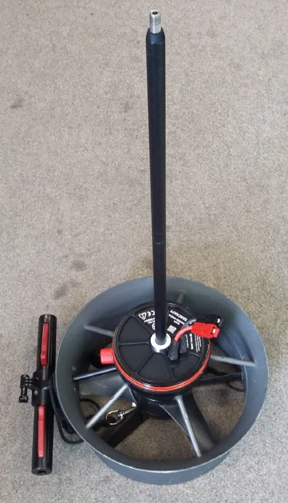
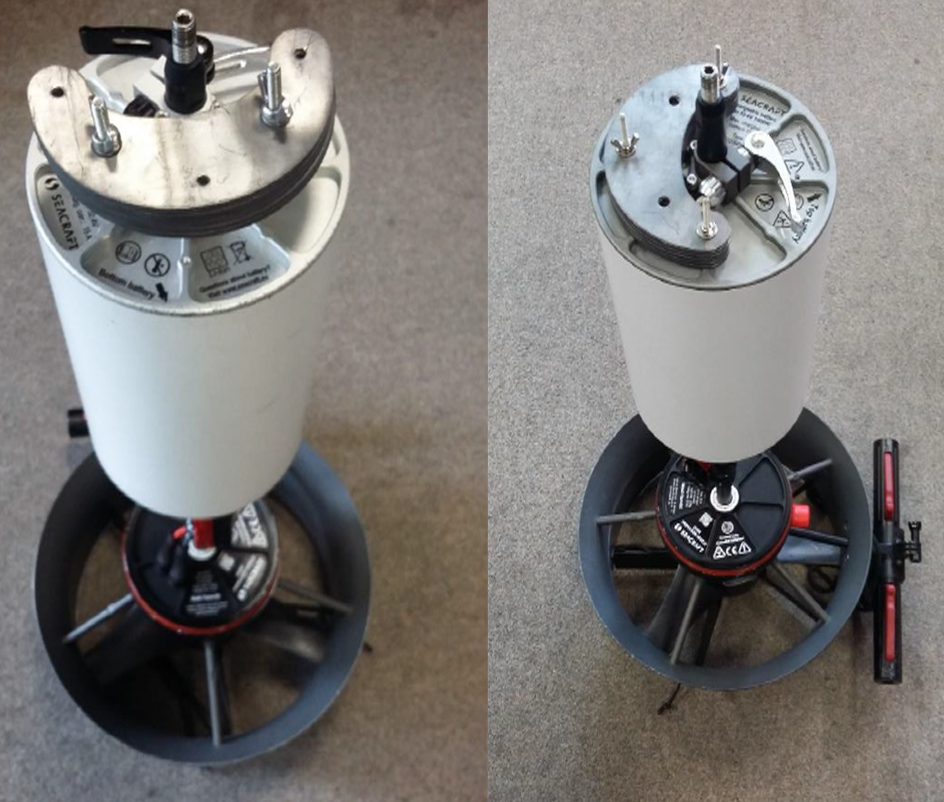
The axial pipe is the “backbone” of the DPV and acts as the mechanical connection between the hull and the DPV’s drive unit, as well as a locking system.
Check if it is not flared, straight and tight. In case of slack, this can indicate a damage of body-axial pipe connecting screw. In case of breaking it, it’s removal is a difficult process.
Disassembling the axial pipe
Using a size 15 fork wrench, or Knipex/ other locking pliers with soft surface, gently unscrew the axial tube.
If you need to disassemble / assemble the axial pipe repeatedly (e.g. for air transport), you may also use the service key delivered with the DPV. Make sure the thread of the the axial pipe top part does not loosen when using the service key.
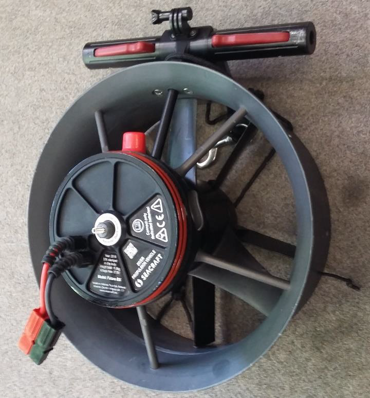
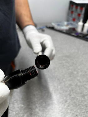
After unscrewing the axial tube, the drive unit with the connecting screw remains:
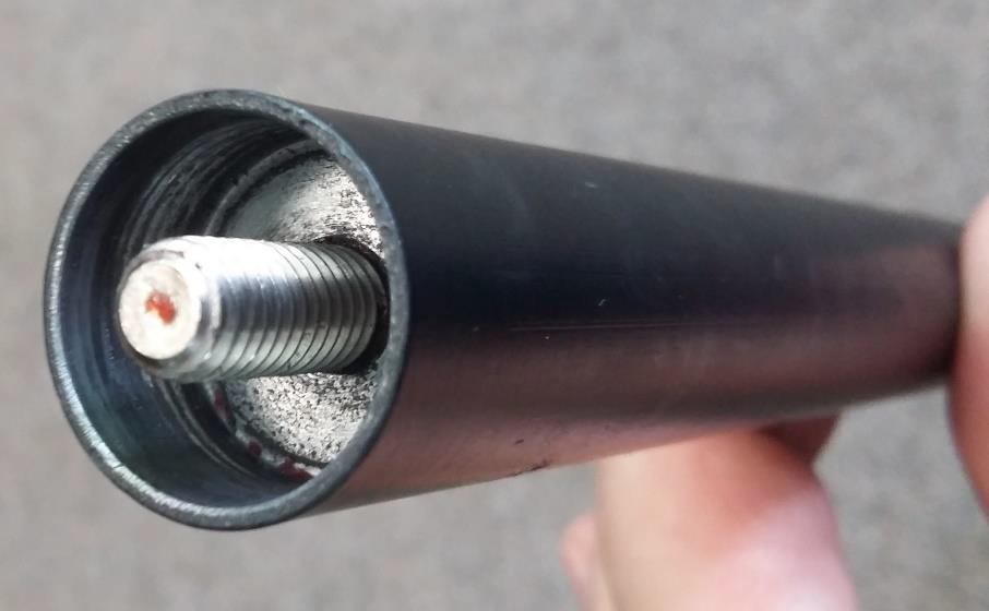
It is possible to encounter other axial pipe systems:
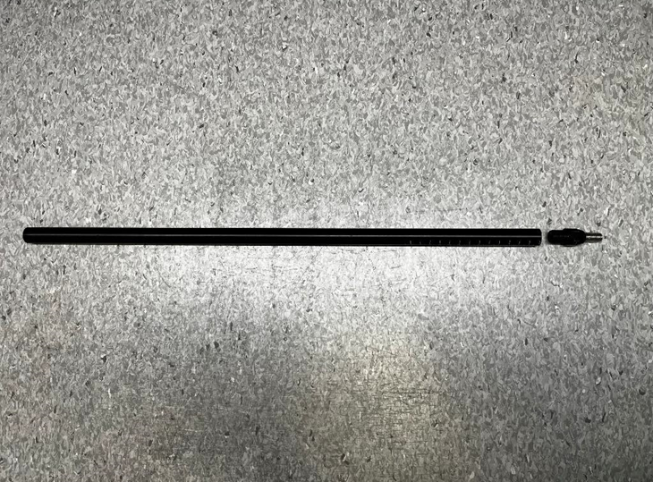
A hollow pipe with a long rod inside is discontinued due to tendency of flaring.
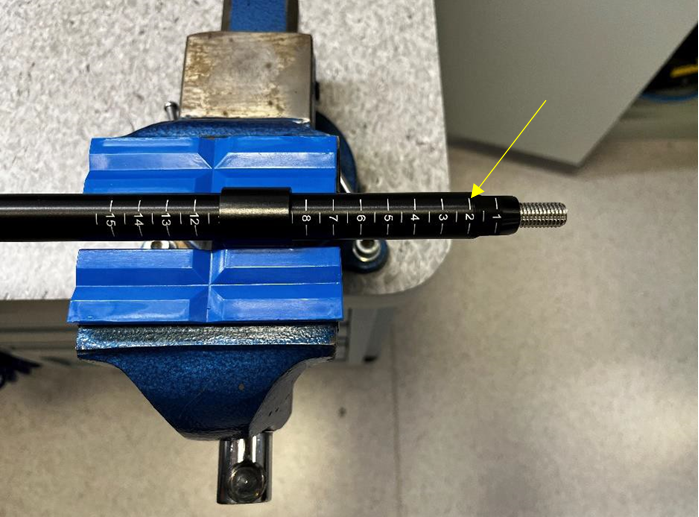
A threaded-end tube is the curently used (from 2022) solution for all DPV’s- facilitating the removal, and reassembly process. It’s working principle and actions needed are the same as with the ‘screw’ type of axial pipe.
Assembling the axial pipe
Apply activator and thread adhesive (soft) to the protruding screw connecting the drive unit to the axial pipe. If the screw stays in the pipe, apply adhesive and activator to the screw protruding from the tube.
To screw on the pipe, first use the Allen key (service key included) on the front screw (M10 x 40 DIN 913). In the final tightening, use a torque wrench set between 10 and 12 Nm.
See the instructional video:
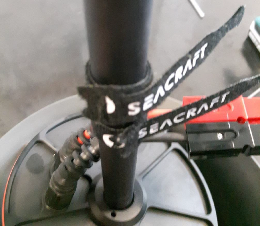
Slide the two velcro strips holding the electric wires onto the tube.
In case you have removed the battery retaining clip during disassembly of the axial pipe, place it now at the previously marked location.
Apply and properly set the battery and ballast.
For the hollow axial pipes – it is recommended to replace them for a full construction.
For the threaded axial pipes – use soft threadlocker in minimum amount to secure the connection. Thereded axial pipes are used in DPV’s above serial number #379.
Troubleshooting
Axial pipe top-part unscrewed itself
If the top part of axial pipe got unscrewed instead of the bottom one, you can follow the manuals below in order to fix it.
Unscrewing the axial pipe
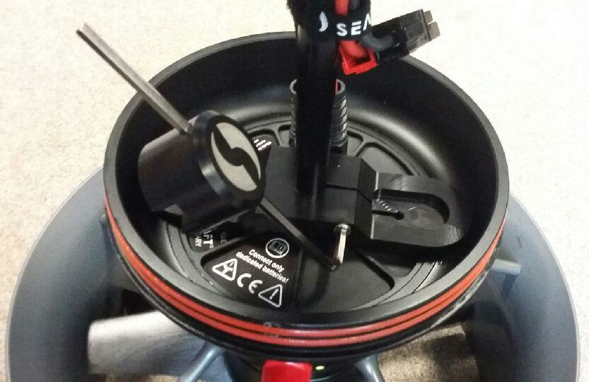
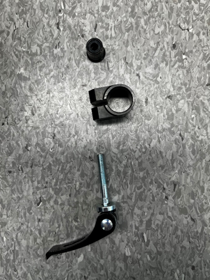
Start from removing the battery positioning clamp.

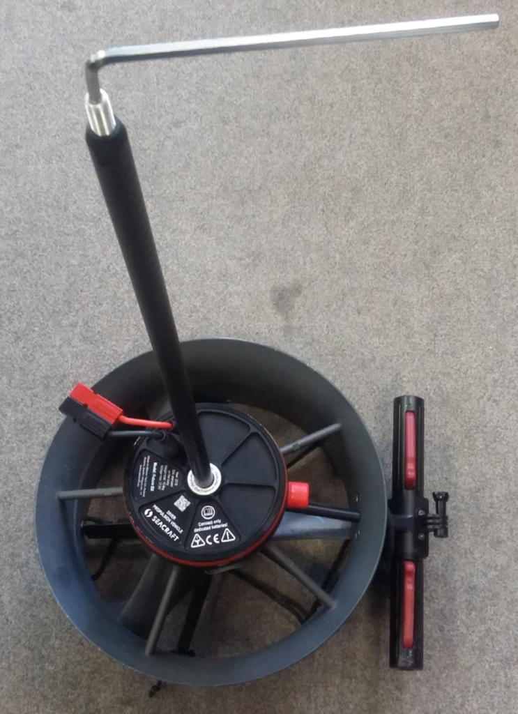
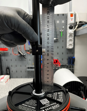
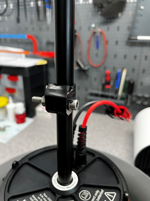
Unscrew it’s parts, and exchange the bicycle style clamp locking mechanism with a M6 x 35 DIN 912 screw, and two washers- as shown below.
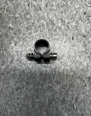
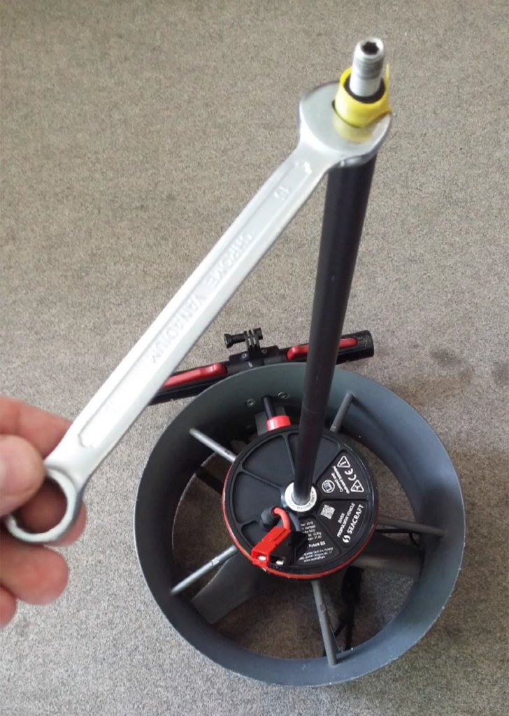
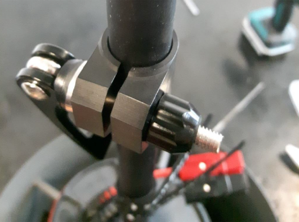
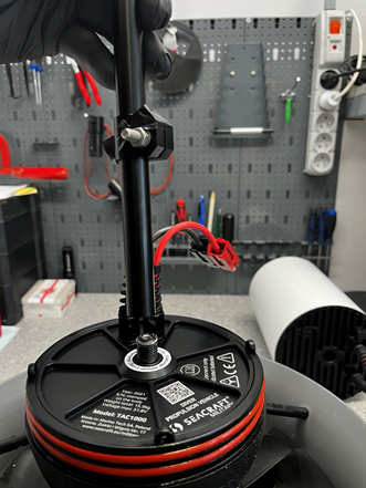
Install the modified clamp on the axial pipe at a height of about 100 mm from the electronics coverplate, measured from the lower edge of the clamp (photo 4). Tighten moderately so that the clamp does not turn as you unscrew the axial pipe.
Secure the upper edges of the clamp with insulation tape so that they will not get damaged when unscrewing.
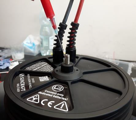
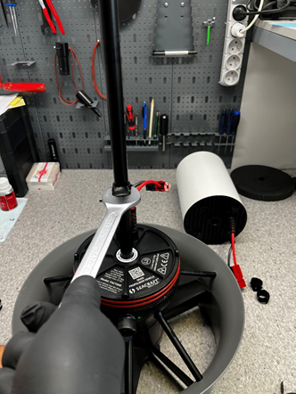
Use a 22 mm spanner on the protected parts of the clamp and unscrew the axial pipe of the scooter.
Re-assembly of the axial pipe top-part
After succesful removal of axial pipe, the reduction need to be correctly reassembled.
Start by removing all of the remaining threadlocker from both parts.
De-grease the surfaces using a prefered solvent, or threadlocker activating liquid.
Both parts should freely screw in, without any resistance.
Apply threadlocker CX-80, or comperable (high strenth threadlocker) to the shown places, in medium amount.

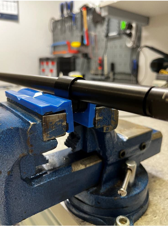
Using the soft-holding mount in the vise, and battery mounting clamp – immobilize the axial pipe. Soft-mount protects the clamp anodisation.
Secure the wrench slot of the reduction with insulation tape (to protect anodisation) and tighten using wrench 15.
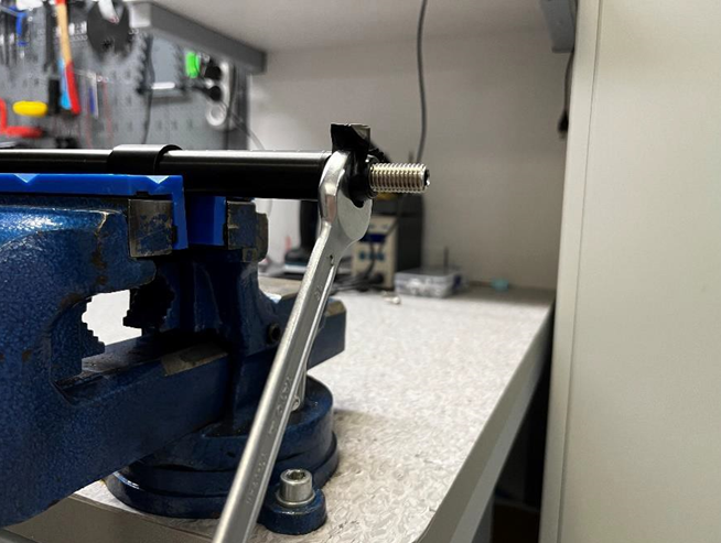
Using moderate strenght, tighten the top reduction until the markings will meet.
In case that any threadlocker is flowing out, clean it.
For final assembly instructions, refer to the manual. Prior to re-assembly, make sure to install the top part according to specific instruction.
In case of questions or problems,
do not hesitate to contact us: service@seacraft.eu.